Functional models
Vehicles
Vehicles are 3D models that lock onto railway tracks or roads. Locomotives and cars will have an engine and may move under their own power, and coaches and wagons will move passively only when pulled.
To bring up the Model Editor, select the model, then go to the Catalog menu, drop down to the 3D models item and choose New from Selection. The Model Editor is also invoked when importing a new model. The paid-for version of 3D Train Studio is necessary for this functionality.
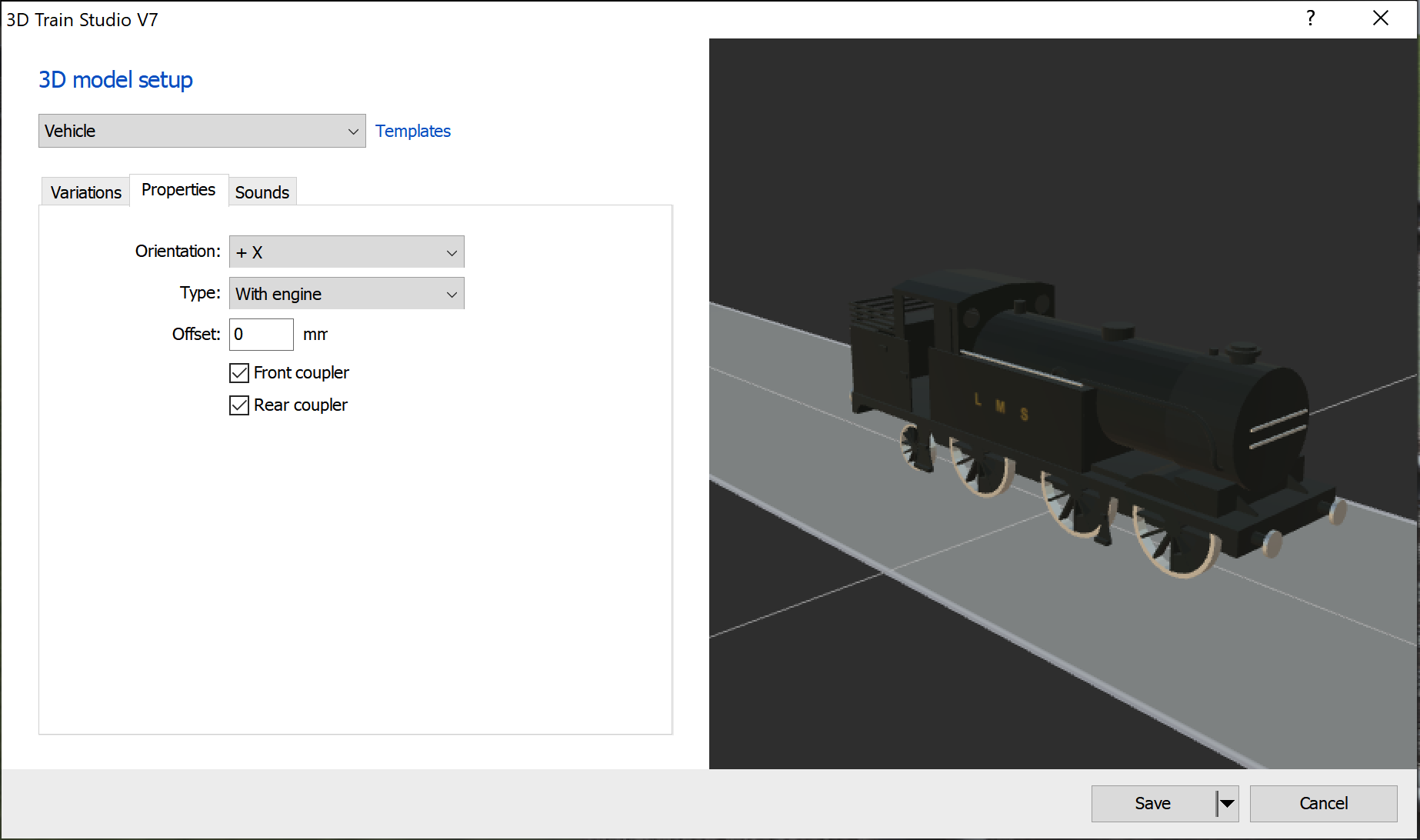
Properties
- Orientation – The direction of forward travel of the vehicle, ie the front. New vehicles should be created with their orientaion along the +X axis.
- Type – Whether the vehicle is self-propelled (locomotive, car) or does not have an engine (coach, wagon, trailer).
- Offset – The distance from the bottom of the vehicle to the top of the rails or to street level. This enables, for example, the correct positioning of wheel flanges.
- Steam Particles – This option appears only when the model includes a _PEP special object. Allows the configuration of steam particles for steam locomotives or vehicles with exhausts.
- Front coupler / rear coupler – Couplings allow other vehicles to latch on and be towed. Deactivate, for example, for cars that do not support trailers, or for people walking. Otherwise automatic distance control does not maintain the required distance.
Special objects in the model
- _Wheel – Defines a wheel that is automatically rotated by the studio depending on the speed of the vehicle. Can also be rotated using its own animation, see below.
- _WheelSet0 / _WheelSet1 – Defines a bogie that is automatically aligned with the track. If specified, both bogies must be defined, where _WheelSet0 denotes the front bogie and _WheelSet1 the rear bogie.
- _Coupler0 / _Coupler 1 – Defines the coupling points at the front and rear. If not specified, vehicles couple at the front or rear end of the 3D model. _Coupler0 designates the front coupling in the direction of travel, _Coupler1 the rear coupling in the direction of travel. Coupling objects are not displayed by the studio, only the positions count.
- _CCP – Cockpit Camera Position, indicates the position of the camera within the model when the user switches to the cockpit view. If you do not specify a position, the studio will choose its own position.
- _PEP – Particle Emitter Position, indicates the starting position for vapor particles.
Special animations
- _AnimWheel – Animation time depends on the wheel rotation e.g. for rod animation or as a replacement for _Wheel.
- _AnimRun – animation is played once as soon as the vehicle starts moving.
- _AnimRunLoop – Like _AnimRun, but is played in an endless loop.
- _AnimRunPositive – animation is played once as soon as the vehicle moves forward (e.g. for train lights).
- _AnimRunNegative – animation is played once as soon as the vehicle drives backwards (e.g. for train lights).
- _AnimSpeed – animation depending on the target speed. The middle of the animation corresponds to the speed 0.
Special noises
- _SoundRun – The sound is played as soon as the vehicle starts moving.
Routes and Lanes
The German language manual uses the word “Fahrstraßen” to mean a series of connected tracks or streets leading from one place to another. This is correctly translated into English as “Route”. The manual goes on to use the word “Spuren” to mean a lane within a model. For example, a model of a single carriageway road might have two lanes. Unfortunately, this word is also translated into English as “Route”, and this is confusing.
Tracks/Streets
Tracks and streets define 3D models that have lanes to guide the movement of vehicles. The user can curve the model dynamically. This is called a spline. Splines may also be set for models without vehicles, such as viaducts, fences and platforms, so the user can extend or curve the model to suit the layout.
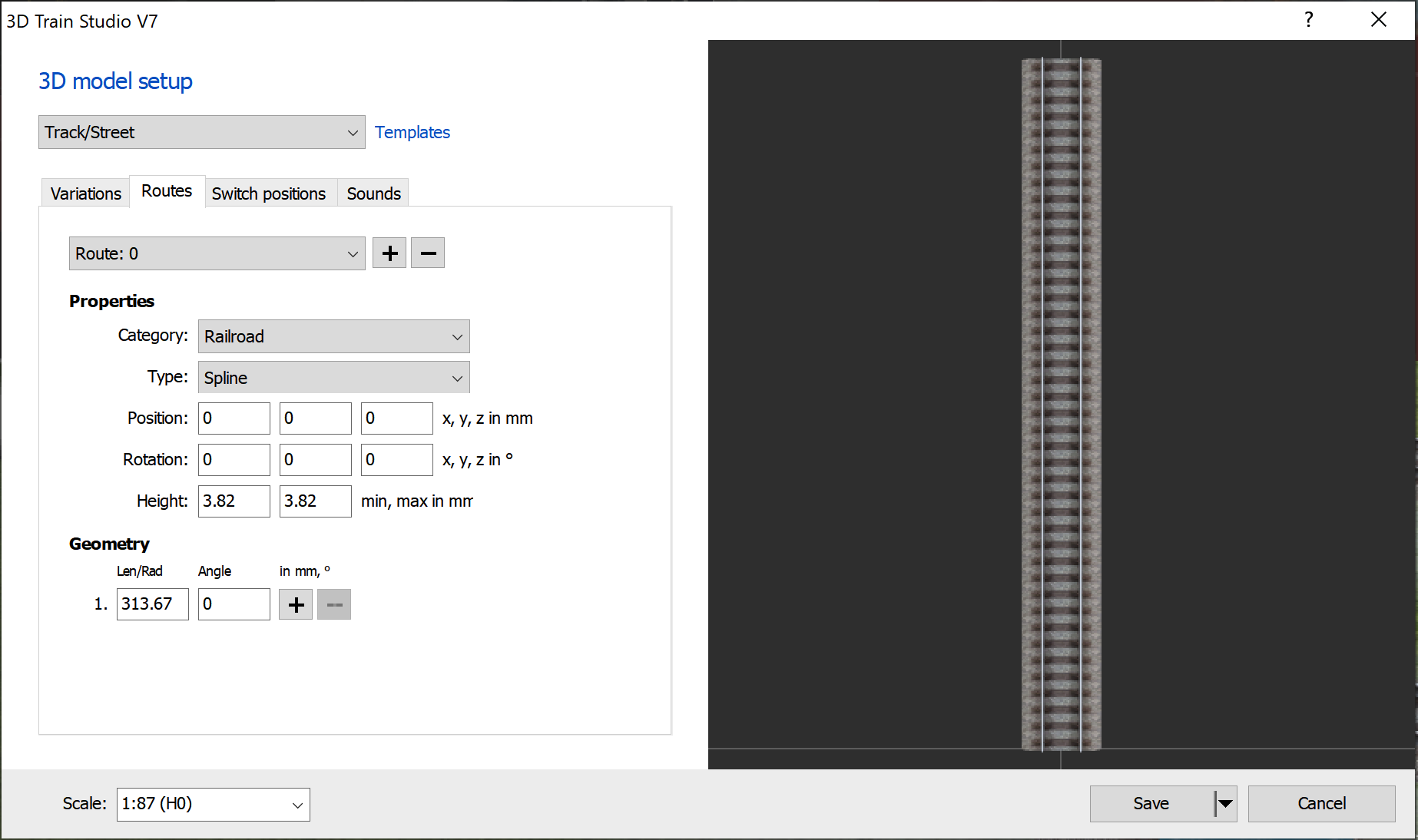
With the help of the tracks and points, a wide variety of track and road objects can be defined. Animated turntables and transfer platforms, bascule bridges for railways, roads with several lanes that can be dynamically bent like a flexible track, etc. are possible, for example.
Lanes
The dialog box for 3D model setup uses the words “Routes” and “Route” but in this context it means “Lanes” and “Lane”.
- There is a limit of 24 lanes per track or street.
- Category – Defines the category of vehicle for which the lane could be used. All the categories, except “3D model only” are compatible with each other. The “3D model only” category is used only to specify the shape for curving the 3D model, and cannot be used as a lane for vehicles.
- Type
- Spline – The 3D model may be stretched and/or curved along the lane along the +Y axis. Only 3D models that are not animated are supported. If stretched too far, a copy will be spawned.
- Spline (rigid) – From v7. Like spline, the model may not be curved along the spline, but it may be stretched in a straight line. If stretched too far, a copy will be spawned.
- Virtual – The 3D model may not be curved along the lane. The lane is invisible.
- Virtual (Animated Object) – Like “Virtual”, except that the lane also takes on the position and rotation of an animated sub-object of the 3D model. The entry only appears for animated 3D models.
- Position – The starting point of the lane on the 3 axes.
- Rotation – The rotation of starting point the lane on the 3 axes.
- Height – The height of any vehicles using the lane. From v5, a different height can be specified for the beginning and the end of the lane, for example to define a lane ramp.
- Geometry – Defines the shape of the lane. Up to 8 segments can be used. Each segment can be either a straight line (angle = 0) or a curve (angle <> 0).
Setting the course
- There is a limit of 24 (from v5: 48) turnouts per track / street
- Actions – List of actions to be carried out when the turnout is activated, up to a maximum of 16 actions per turnout.
- Play animation – A model animation is played up to a certain target time (relative between 0 and 1). Circular animations interpret the times as “circles” and always take the shortest route (as with a turntable, for example), ie a start time of 0.9 and a finish time of 0.1 means a length of only 0.2.
- Activate uncoupling track – Activates the uncoupling property of the specified track. When activated, vehicles in the middle of the lane are uncoupled. If another turnout position is activated that does not have the “Activate uncoupling track” action for the corresponding track, the uncoupling property is automatically deactivated.
- Activate track – Activates a track. Vehicles only enter one track / street via an active lane. If another turnout position is activated that has no “Activate track” action for the corresponding track, the track is automatically deactivated. If there is no “Activate track” action for a track in all turnout positions, the track is considered to be permanently active.
Scale
Tracks can be limited to a certain scale if, for example, they are replicas of real model railroad tracks that are only available for certain nominal sizes. In the case of a scale restriction, the scale is retained even if a different one has been selected on the layout. The 1:1 scale is an exception. In this case it is assumed that the user is not interested in model railroad scales, which is why tracks with scale restrictions are also converted to the layout scale.
Particle effects
With the help of particle effects, dynamic objects such as smoke, fire or clouds can be generated.
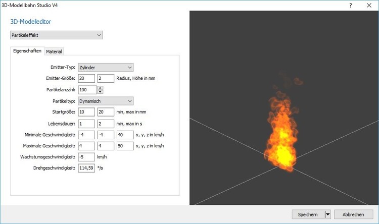
Properties
- Emitter type – Specifies the shape of the particle effect, the area in which new particles are created. This can, for example, be cuboid, cylindrical or spherical. When a new particle is created, its position is randomly determined in the specified area.
- Emitter size – Indicates the size of the emitter, depending on the type selected.
- Particle count – Indicates the total number of particles per effect. The higher the number, the more realistic the effect will look. A high number of particles is at the expense of the CPU and graphics card, which is why the number should be minimised.
- Particle type – Specifies how the particles move. Dynamic particles have a speed and a “life span”. When this is finished, the particle is created in a new position. Static particles have no lifespan or speed and therefore do not change (e.g. clouds or fog).
- Start size – Specifies the minimum and maximum size of a new particle. The actual value is determined randomly in this area. The larger the area, the more diverse the particles.
The following settings only apply to dynamic particle effects:
- Lifetime – Specifies the minimum and maximum lifespan of a single particle in seconds. The actual value is determined randomly in this area. When the life of a particle ends, it is generated again at the starting position with new random values.
- Minimum speed – Specifies the minimum speed of a particle in all 3 directions.
- Maximum speed – Indicates the maximum speed of a particle in all 3 directions. The actual speed lies between the minimum and maximum and does not change in the life of a particle.
- Growth Rate – Indicates the rate at which a particle changes in size per second. Negative values cause the particle to shrink over time, positive values make the particle larger.
- Rotation Speed – Indicates the rotation speed of a particle.
Material
- Texture – Specifies the texture to be used for each particle. There is a selection of particle textures in the “Material” category in the catalog.
- Start colour with transparency – Specifies the colour and transparency of the particle at the beginning of its life.
- Target colour with transparency (dynamic particles only) – Specifies the colour and transparency of the particle at the end of its life. During particle life, the actual colour and transparency are interpolated between the start and target colours.
- Light particles – Specifies whether the particles light up. Luminous particles (such as fire) are not influenced by the light from the system. Luminous particles have no transparencies, since the colour alone determines the appearance, ie a black “luminous particle” is not visible, a white “luminous particle”, on the other hand, contains the lightest colour.
Barriers
Barriers are 3D models that automatically open and close when a train approaches. The detection area is specified by the studio. Note: barrier models should be avoided as they will be removed in a future release. In the future, preference will be given to animated 3D models that are individually controlled in combination with track contacts.
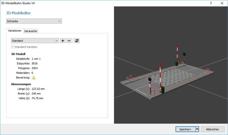
Special animations
- _AnimBarrier – is played when the barrier opens or closes (initial state open, animation forwards when closing, animation backwards when opening).
- _AnimBarrierClosed – is only played while the barrier is closed, but in an endless loop.
Special noises
- _SoundBarrier – Will be played in an endless loop while the barrier is closed.
Signals
Signals are animated 3D models. The animation is controlled by signal aspects defined by the model builder. Each signal aspect corresponds to a point in time within a global animation. The signal aspects are evenly distributed over the total time. The first signal aspect corresponds to the beginning of the animation, the middle signal aspect corresponds to the middle of the animation, and so on.
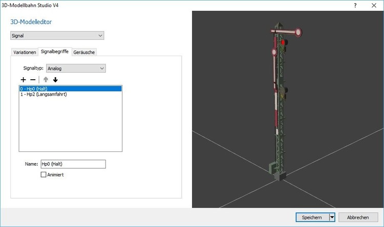
Signal aspects
- There is a maximum of 24 aspects per signal.
- Signal Type – Indicates whether the signal is analog or digital. Analog signals play the animation slowly. Digital signals jump immediately to the corresponding signal aspect without intermediate animation steps.
- Animated – Indicates whether the signal aspect itself is animated. In this case, the global animation is played in an endless loop between the current aspect and the last animation frame before the next aspect, for example, for flashing signal aspects.
Special animations
- _AnimSignal – References the global animation, which contains all signal aspects.
Tax objects
A control object is a 3D model that assumes various states and can pass these on to linked objects such as switches, signals or vehicles, which enables these objects to be controlled.
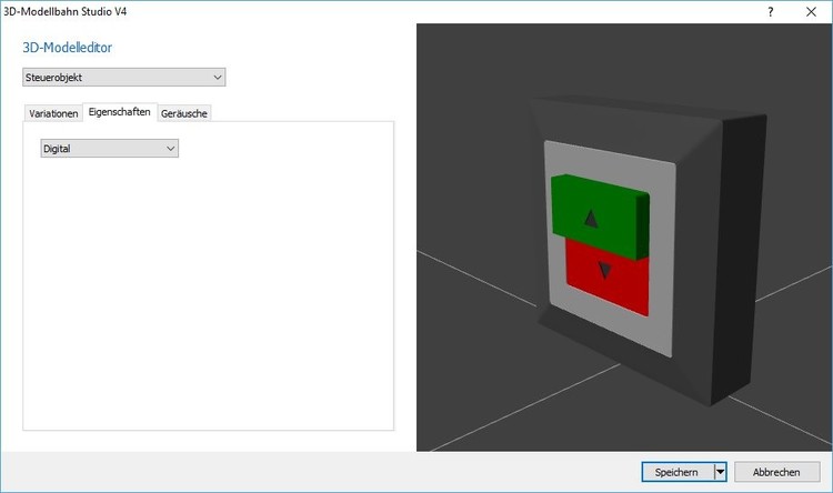
Properties
- Analog / Digital – Indicates the type of control object that determines the possible states. Analog control objects such as rotary controls have continuous values, while digital control objects such as switches always only have discrete states (eg on / off). Analog objects can therefore be used, for example, for vehicle speeds, with such a rotary control continuously regulating between “maximum speed backwards” and “maximum speed forward”. Digital objects can be linked with switches or signals, for example, which then control the switch positions or the signal aspects.
Special animations
- _AnimValue – animation time is based on the current state of the control object. The lowest value corresponds to the beginning of the animation, the highest value corresponds to the end of the animation.
- _AnimSwitch , from V5 – With digital switches, it is played once from the beginning whenever the status changes. These animations can be used to display buttons that change back to the starting position after being pressed (but still save different states internally).
Special noises
- _SoundSwitch – is played when a digital control object changes state.
Cranes
Cranes do not represent an independent functional model, but can be used for all functional models (vehicles, tracks, signals …) and enable goods to be transported. In the forum, EASY clearly describes the construction of a crane with a blender.
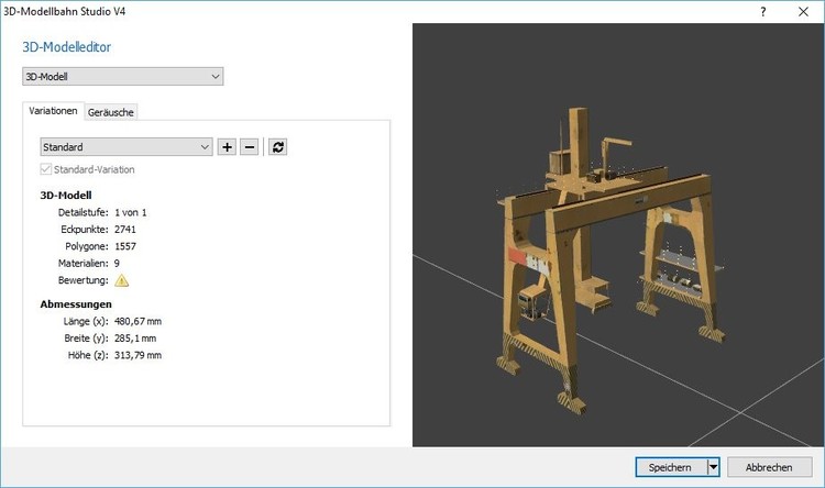
If a crane model uses one of the following special objects, the crane functionality is activated automatically.
Special objects
- _Crane_Hook / _Crane_Hook_Bottom – The object is considered a hook. In this case, the crane grabs the transported goods from above. If the object is called _Crane_Hook_Bottom, the crane attacks the goods at the lowest point (eg a forklift). The target object is linked with the check mark.
- _Crane_Reach – This object is used to visualize the catchment area of the crane. The object is automatically displayed in planning mode as soon as the crane is selected. The object is hidden in simulation mode.
- _Crane_AnimRef – The start and end position of the object specifies the extreme values of the corresponding animation. Normally, the studio calculates the start and end positions of an animation by averaging all objects affected by the animation. However, if the reference point deviates from the center point, the center point can be specified explicitly by placing the special object. The special object is automatically hidden by the studio.
Special animations
- Always start with the string _Crane_
- Followed by a number indicating the order of animation.
- This is followed by the movement type, _Tra , _Rot , _Ori or _Siz_X_Y for translation (movement along an axis), rotation (rotation around an axis to a target point = rotating crane), orientation (rotation for orientation on the target object = rotation of the hook) and size (adjustment the hook size on the transported goods, where X is the minimum size and Y is the maximum size in whole-numbered millimeters)
- Rotations or orientations can be restricted with _NoWrap in such a way that they do not always take the shortest route, but remain in the specified angular range (e.g. for a derrick crane).
- Standard orientation : With _Rot or _Ori , a _X or _Y can be appended to indicate the standard direction in the 3D model, otherwise the studio does not know “where” a crane is looking by default.
- _Hold for animations that are played when the crane goes to the waiting position
- Important, all animations must have linear ease-in and ease-out, so they must not slow down at the beginning or the end, but must move over the entire area at a constant speed.
- Example – _Crane_1_Rot_Y_Hold describes a rotation animation with standard orientation in Y and is part of the waiting animation
Special noises
- _Crane_Run – Will be played as long as the crane is in motion.
